Houdini
Houdini is a 3D animation software application developed by Toronto-based SideFX, who adapted it from the PRISMS suite of procedural generation software tools. Houdini’s exclusive attention to procedural generation distinguishes it from other 3D computer graphics software.
File/Properties
The 3D file format retains only the most basic information about geometry, appearance, scene, and animation. It uses a triangular mesh to encode the surface geometry approximately. A 3D file format is used for storing information about 3D models. You may have heard of the most popular formats STL, OBJ, FBX, COLLADA etc. They are widely used in 3D printing, video games, movies, architecture, academia, medicine, engineering, and earth sciences.

Merge
This node merges together the geometry from its inputs into a single stream of geometry, which you can then send through other nodes. If you need to continue distinguishing different parts of the merged geometry later, try using the Group node to put the input geometries into groups before merging them.

Replacing
3D modelling is a technique that may make it easier for you to produce future projects. After equipment libraries are built according to client specifications or utilising manufacturer information within a 3D application, new designs may be quickly built or updated.
Viewports
3D Modelling not only help designers and end users see space requirements, but it also improves drawing efficiency and accuracy. The designer can see what they would not be able to see in 3D when working in 2D. Also they can rotate the camera however they want to get the best view on the model.
Saving
We need to save the files so we can continue our work. There are certain actions after what there is an automatic save, but usually you need to save the file every time you do something important as your progress can be lost by a simple crash.
Viewport Configuration and Controls
You can always change the keys you use to navigate around the object you are modelling. These keys could also be changed at any time in settings. In houdini by default you control it with your mouse, it helps it to move around, also if you want just to move a little bit your position you could keep using your mouse but with holding “shift” button, mouse wheel button also can move your 3D Model to a different positions.
Keyboard Shortcuts
Most of the functions have a shortcut to ease your work and to make it more efficient, as I mentioned above you can change them at any time in settings. Beside the shortcuts with the mouse wheel button there are a lot of others useful shortcuts: “E” for scaling, “T” for moving, “R” for rotating…etc.
Customising the Interface
Some 3D Modelling software allow you to configure the app for yourself, which will give you a more pleasant view. It means it will give you the possibility to change the background colour of the app.
Toolbars
Houdini has a lot of functions and attributes which ease the 3D Modelling and allow you to do one thing in a lot of different ways. Below you can see a small part of Houdini’s features.

Object Naming Conventions
Asset names should come primarily from the file names that get uploaded. It would be best if assets are only renamed when necessary to match with a renaming of the actual source files as well, or for other specific purposes. The naming convention that can be used with the file names can vary from project to project.
Grids
Houdini has two grids: the reference plane which helps you orient yourself in 3D space, and the construction plane which tools place things relative to.
Drawing Units
Usually, you choose the type of units that you normally use to talk about whatever you’re drawing: feet and inches for a building in the United States, millimetres for almost everything in almost all the rest of the world, and so on.
Geometric models and text
Houdini provides default objects to use in 3D modelling, those are: boxes, cylinders, discs, tubes, spheres or 3D text. These things can be used to design anything you want. In my case it was a 3D model of a dagger, for this I have used only a tube, and I modified it. I will explain below the modification I made to it.

Mesh Building and Editing
- Vertex – It is a point placed in the space. More than one vertex are called vertices. With the 3D cube, for example, the vertices correspond to the corners. They define the shape.
- Polygons – are an approach for modelling objects by representing or approximating their surfaces using polygon meshes. Polygonal modelling is well suited to scanline rendering and is therefore the method of choice for real-time computer graphics.
- A planar model of a compact surface is a disc whose boundary is a 2n-gon whose edges are identified in pairs.

Modelling

I will show you step by step how to develop a dagger exactly like I did. And first thing you need to do is to add a tube and on the right part of the screen increase the number of columns to 50 because we will need this for the next steps.

Now choose the whole tube and use “Polyextrude”. Extrude it in a way to get an ring like below:

Now you need to use Polyextrude again. But select only 1/4 of your primitives around the tube, and drag this part out of the tube to get this:

Next thing we need to do, is to change the selection of primitives on the left part of the screen, to selection of points. We select the first and last point above and below of the part we extruded and press shortcut “T” to move this a little back. Then we select all the remaining points, except those we used for the previous manoeuvre, and we use T again to move it forward, to get something like a blade. Also use shortcut “E” to make the blade wider or tighter.

Change now the selection of points to edge selection, and choose the deep edge between the blade and tube. And Polybevel it. We need to do that to make that edge rounded, so it will look more satisfying.

Change now the edges selection to primitives selection and Polyextrude it like we did before, but on the other part of the tube, this will be the handle of the dagger.

Now you have to do actually the exact same things, but don’t do it that sharp on the top. Try to make it look like a simple knife or kunai handle:

Now let’s go back to our blade. Let’s give it some realism, try to make it sharper. Select the whole primitives of the blade and press E or choose “Scale”, move it down to make it as sharp as possible, or as sharp as you like it. In my opinion this is the best for my dagger:

Choose all the primitives around the handle and play with it’s scale until you get the perfect one for you. You can compare it to how it was, you will definitely see some changes.

And let’s now use Polybeveling on the edge between the handle and the tube. What I forgot to mention, when we were Polybeveling the edge between the blade and tube we changed the “Divisions from 0 to 20” and “The distance from 0 to 1″. In the case with these edges I think will be enough 10 divisions instead of 20 like we did above. On the right part of the screen you can see in the squares with red border the distance and divisions:

Basically the dagger is done, we just need to colour it. And we can do that by pressing right click on the right part of the screen, below. And type “color”. Then you can press on the pointer there and choose all the primitives you want to colour. I’ve chosen the blade and coloured it into a dark blue, which looks like grey. Then we do that again to choose the handle colour and one more time if you want to colour the tube with different colour.

After these actions we add next 3 attributes: Divide, Normal and Simple_Baker. Divide we need to change the number of edges on our model. On the screenshot you can See I have chosen 10.

Next attribute “Normal” we need to increase or decrease the cusp angle of our model. It will add more or less shadows to it.

And the last one, “simple baker”, has the role of rendering. We need to choose the resolution we need and path where we want the file to be saved. Then press render button, which is on the top left of the screenshot:

Virtual Camera
I have added two cameras, so I can try to render it using “mantra”. To choose any camera view you can press where I show on the screenshot and choose your camera. Here is the field view from the first camera:

Camera Parameters can be changed on the right part of the screen, where you see numbers on the coloured lines. Or you can set the camera however you want on the main screen, just by dragging it where you want.
Camera type – there are different camera types here, VR Camera, gamepad camera, simple camera which I have used, and some others. They are all used for different purposes, for creating a VR Game or something using the gamepad.
Lighting
I decided to add some lights to the knife and around it.
Inside the tube of the dagger I have added a pointlight, which serves like a simple weak flashlight inside there but it is invisible.

Next one is the spotlight, this one works like a bigger lantern, it gives light over an area which you choose. Like the lanterns on the street in the night.

The area light is almost the same as the previous one, the spotlight. It just covers a bigger area, and obviously offers you more light. It looks a bit different comparing to the spotlight and easier to set up. You can change the area light shape by changing the Light type parameter. Use the Area size parameter to set the size of the light.

Last one that I have used is the environment light, and it gives you light over the whole environment.
Environment lighting adds light to the scene as if it came from a sphere surrounding the scene. The light is usually colored using an image called an environment map. An environment map can match the lighting (and reflections) in a scene to a real-world location, or may simply be used to add interesting variation to the scene’s lighting.
In a PBR rendering setup, realistic environmental lighting is cheap to render.

Texturing
A 3D Texture Artist creates stylized or natural textures and materials that are then applied to 3D models and environments in games, films, or TV shows. They play an important role in the VFX Pipeline. Whether texturing game models or film assets, Texture Artists use a variety of texturing software and techniques.
I don’t have any textures in my project, but lets see how it works. After the artist creates the required textures, he is uploading them to the 3D Modelling software, and then he apply them to the objects he is supposed to.
- A 3D material is basically what you layer on top of a 3D object, to control the way the object is perceived when rendered. It behaves much the way a material does in the real world – whether that’s the way light interacts with its surface, or the nuances of colour, texture, transparency and reflectivity
- 3D mapping means profiling of objects in three dimensions to map the objects in real-world. There are several ways for a 3D profiling of an area or object, such as using a pair of a stereo camera. Another method is to measure the depth of an object or feature from focus.
- A Material Editor is a node-based graph interface that lets you design shaders for your geometry, such as Static and Skeletal Meshes, or for use with other systems like Cascade to generate unique materials.
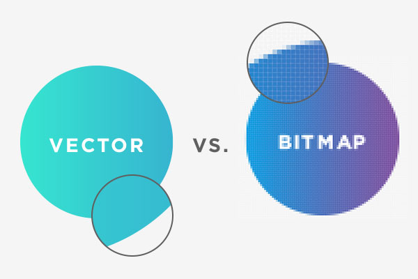
Bitmap. Because of the amount of data that each pixel can contain, bitmaps are ideal for making detailed pictures . The wider the range of colours it can display, the more data there is.
Render
An image of a 3D scene can be generated in multiply ways, but of course any way you choose should produce the same image for any given scene. In most cases, the goal of rendering is to create a photo-realistic image. I will attach below a picture of my rendered dagger. I did it just by clicking render on the top of the screen and it has rendered using “mantra ipr”.

By publishing HTML output to the response stream, the Render method allows the controller to render itself. It allows the consumer of your class to render it, and if you’re using a composite control, you can use it to draw the child controls as well.
Generally, modern render can be divided into three main types: mineral, acrylic and silicone – but there are other options.
The safe frame shows the area of the viewport that will be rendered in the active viewport. If parts of the rendered view are off-screen, the safe frame will indicate this by displaying arrows either at the top and bottom or left and right. Shows the size of the rendered view as a yellow frame in the viewport.
The aspect ratio of a photograph specifies the proportional connection between the image’s width and height. Aspect ratios are commonly used in photography and movies, and many of the products in your surroundings use them. The output size is also compatible with aspect ratio; however, it is dependent on the resolution.

3D Modelling most common file formats:
- STL.
- OBJ.
- FBX.
- COLLADA.
- 3DS.
- IGES.
- STEP.
- VRML and X3D.
File Size. It is important to have a light file, which will not have too many GB. We must take care of it while designing the 3D Model as it has more polygons it will make the file heavier.
Compression. Some picture formats allow you to compress the image to save space on your hard drive.
Web Rendering
Rendering is a process used in web development that turns website code into the interactive pages users see when they visit a website. The term generally refers to the use of HTML, CSS, and JavaScript codes. The process is completed by a rendering engine, the software used by a web browser to render a web page.
Video Rendering
Video rendering refers to the process through which a computer system methodically processes information from a coded data source to transform that information to put together and display an image. In other words, rendering converts the source material into the final picture or footage.
Image Resolution
Image resolution is the detail an image holds. The term applies to raster digital images, film images, and other types of images. Higher resolution means more image detail. Image resolution can be measured in various ways. Resolution quantifies how close lines can be to each other and still be visibly resolved.
Industry Practice
Reflect on finished product, compared with original intentions
I expected 3D Modelling to be easier, actually it is not hard, it just has a lot of functions, features and attributes that needs to be understood. I have already started understanding them and feel like could do something way better in the future. But when I was designing/drawing this knife I have expected it to be easier, and also I didn’t even see that I should have had a gap into the blade. I am happy with the model I have done and consider it a good one for the first time, for the time when I was trying every attribute, trying to see what it does, especially after I have already finished the model, the knowledge about this software was easier to understand for me. The quality of the dagger can’t even be compared to the original, mine looks only like a early version of this dagger. I wanted to develop an animation which will move the dagger in different ways, and decided to do it simply by following a path. This path could be rotated in a ways so it does some flips or any other cool animation, but it requires time and coordination with the path points.

Production Skills
This software requires a lot of knowledge and skills, it is not hard to get these once you start using it. This is what I would like to do in the future, it is attracting and I have this feel when you want to dig deeper and deeper, to find out something new, in my case I want to find some new features about this software, to understand better its functionality. As I said, for the first time I consider it not a good model. I have used only a tube to make it, I wanted to do it like this because I knew everyone will use at least 3 shapes and connect them, but I wanted to modify one shape as much as possible to see how far can I go with it, and I have got the answer for myself.
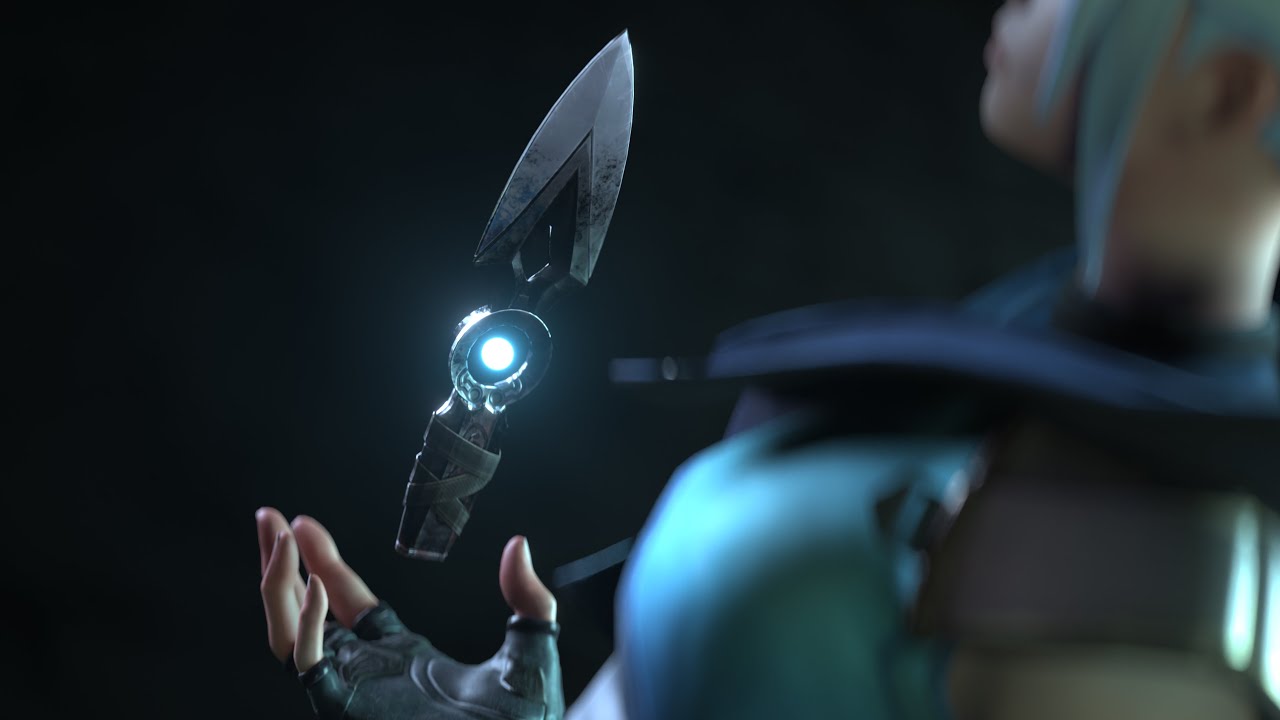
The idea to do this dagger came from a FPS Game “Valorant”. There is a similar dagger, but it is way better designed.
The specification was to design and animate an object which could be used for something. I think I did that, it could be used in a game if I change the animations and if the game will not require graphics like CyberPunk 2077 😀 .
Workflow was pretty good, I just needed to get started because once I do the first steps I can continue by myself, I just need to understand the basics, and I did it. Classmates appreciated the model I have done, and some of them even asked me for help because they couldn’t understand how to do some things, I gave the some advices or helped them when they asked for help.
I feel inspired now and I want to design more things in 3D to try to get better. I understood that houdini is a really cool software for 3D Modelling, it offers huge opportunities and many ways to do what you want.
For myself I have used the videos from google classroom and the video which I will attach below:
